Configurable UART Transmitter and Receiver
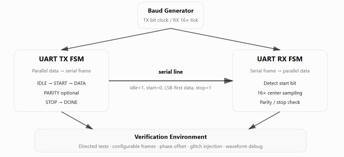
I separated the transmitter and receiver into independent state machines and used programmable counters for the bit timing. The receiver runs from a 16× sampling tick so it can locate the center of each asynchronous bit instead of sampling directly on a nominal baud edge.
- Data length
- 5–8 bit
- Parity
- Odd / even
- Receive sampling
- 16× oversampling
- Baud range
- 4.8–57.6 kbaud
- Verified configurations
- 50
Transmitter
The TX FSM latches the input word at the start of a frame and sends one start bit, 5–8 data bits LSB first, optional parity, and one or two stop bits. Separate counters track baud ticks and the selected data length.
Receiver
The RX input is synchronized before the FSM looks for a falling start edge. The start bit is checked near the eighth sample, and later data, parity, and stop fields are sampled near their centers before data-valid is asserted.
Verification
I tested TX-to-RX loopback across 50 combinations of data length, parity, and stop-bit settings, with baud rates from 4.8 to 57.6 kbaud. Additional cases varied clock phase and exercised parity and framing-error behavior.
Verilog · SystemVerilog · FSM · Testbench